Clamping Cylinders

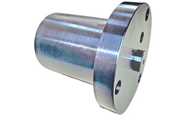
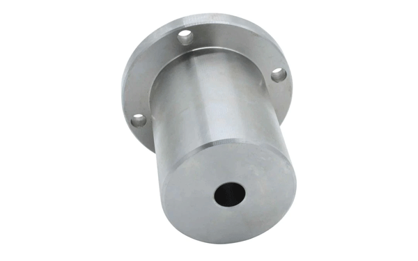
We are Manufacturer, Supplier, Exporter, Dealer, Services Provider, of Clamping Cylinders from Satara, Maharashtra, India.

power-nut-pp
Clamping Cylinder

Hydro-mechanical spring clamping pistons are working with interaction of mechanical and hydraulic systems. The clamping force is applied through preloaded disk spring stack. The pistons are loaded with spring clamping, the hydraulic pressure is required only for the release of spring force. Required movement for the thrust pin is lifting. This system guarantees the greatest reliability because the clamping force is maintained fully independent of the oil pressure or leak-losses. Due to the short operating time the hydraulic system is cost effective. The clamping cylinders provide sturdy and reliable clamping system, that can be used where the sliding or movable machine parts need to be clamped or locked temporarily. Other applications are fixtures for workpiece or tool clamping.


push-pull-cylinder
Operational Principle

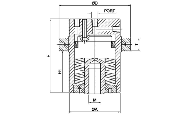
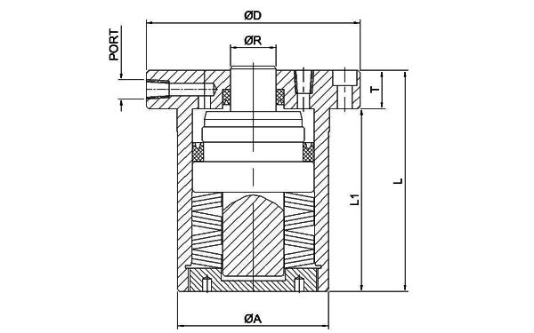
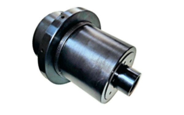
The piston thrust is developed by the disk spring stack. The spring stack is compressed with increasing oil pressure the spring force increases. Under pressure, the corresponding nominal clamping force is reached as a reaction force of the disk spring stack. To release the thrust, a higher hydraulic pressure is required, which, up to a maximum value, is proportional to the release stroke. The setting pressure is required only for precise force adjustment during initial installation. During the actual operating cycle, the cylinders are at release pressure.


Product Features
  • Mechanical clamping
  • Hydraulic releasing
  • High operational safety
  • Leak-proof construction
  • Robust design
  • Spring clamping systems
  • Mounting position universal
  • Economical clamping solution.
Technical Information
  • Clamping Force - 25 to 100 Kn.
  • Operating Pressure - 150 bars.
  • Maximum Pressure - 450 Bars.
  • Operating Stroke - 1.5 to 2.00 mm
  • Product Weight - 2.5 to 25 Kg.
  • Oil Flow required - 2 to 15 CuCm.
  • Temperature range: - 30 - 100°C
push-pull-cylinder
Assembly and Adjustment

To operate a hydraulic unit is needed which should be equipped with a manometer, a pressure cut-off valve, a solenoid valve and a pressure switch unit fill the cylinders and lines at low pressure and bleed (products are supplied without oil) increase system pressure to required pressure, align cylinder using the ring guide nut, setscrews or fitting discs until the thrust piston or the clamp is free from play, fasten thrust piston with screws or secure the ring guide nut on the clamping cylinder release system pressure; set release pressure for the required release stroke; check the release stroke and adjust if necessary


Clamping Cylinder
push-pull-cylinder
push-pull-cylinder
Technical Data
Model Code Dia. A Len - H Dia - C Th - M Dia - D T M 1 Wt. in Kg.
CC D050 0100 50 75 20 M 16 70 16 M 55 x 2 1.37
CC D060 0100 60 90 25 M 16 85 18 M 65 x 2 2.39
CC D070 0100 70 100 30 M 20 100 20 M 75 x 2 3.63
CC D080 0100 80 120 35 M 20 115 25 M 85 x 2 5.65
CC D100 0100 100 145 40 M 24 140 25 M 105 x 2 10.4
CC D125 0100 125 180 50 M 30 175 30 M 130 x 3 20.0
CC D150 0100 150 215 60 M 36 200 30 M 155 x 3 32.9
CC D175 0100 175 250 70 M 45 245 40 M 180 x 3 54.1
CC D200 0100 200 290 80 M 50 280 40 M 205 x 4 80.5
Model Code Clamping Force Kg Max. Stroke in mm Piston Area in SqCm Oil Reqd in CC Release Pressure in bar Port Size
0.5 mm 1.0 mm Max.
CC D050 0100 1500 2 9.60 1.92 125 175 225 1/4" NPT
CC D060 0100 2500 2 15.90 3.18 125 175 225 1/4" NPT
CC D070 0100 4000 2 23.80 4.75 125 175 225 1/4" NPT
CC D080 0100 6000 2 33.20 6.64 125 175 225 3/8" NPT
CC D100 0100 10000 2 50.30 10.06 125 175 225 3/8" NPT
CC D125 0100 15000 2 78.30 15.71 125 175 225 3/8" NPT
CC D150 0100 20000 2 113.10 22.63 125 175 225 1/2" NPT
CC D175 0100 25000 2 154.00 30.80 125 175 225 1/2" NPT
CC D200 0100 35000 2 201.10 40.23 125 175 225 3/4" NPT
Clamping Cylinder - CP
push-pull-cylinder
push-pull-cylinder
Model Code Dia. A L L 1 Dia. - R Dia - D T N x M x P Wt. in Kg.
CP D050 0100 50 75 60 15 70 15 3 x 5.5 x 60 1.37
CP D060 0100 60 90 72 18 85 18 3 x 6.5 x 72 2.39
CP D070 0100 70 105 85 20 100 20 3 x 9.0 x 85 3.78
CP D080 0100 80 120 96 24 112 24 3 x 9.0 x 95 5.61
CP D100 0100 100 145 120 30 140 25 3 x 11 x 120 10.4
CP D125 0100 125 180 145 40 175 35 3 x 13 x 145 20.5
CP D150 0100 150 215 180 45 200 35 3 x 17 x 170 33.4
CP D175 0100 175 250 210 50 250 40 3 x 18 x 210 54.7
CP D200 0100 200 290 240 60 280 50 3 x 22 x 230 82.9
Model Code Clamping Force Kg Max. Stroke in mm Piston Area in SqCm Oil Reqd in CC Release Pressure in bar Port Size
0.5 mm 1.0 mm Max.
CC D050 0100 1500 2 6.50 1.30 130 180 230 1/4" NPT
CC D060 0100 2500 2 11.40 2.28 130 180 230 1/4" NPT
CC D070 0100 4000 2 17.60 3.52 130 180 230 1/4" NPT
CC D080 0100 6000 2 25.20 5.03 130 180 230 3/8" NPT
CC D100 0100 10000 2 37.70 7.54 130 180 230 3/8" NPT
CC D125 0100 15000 2 58.90 11.80 130 180 230 3/8" NPT
CC D150 0100 20000 2 84.90 16.97 130 180 230 1/2" NPT
CC D175 0100 25000 2 115.50 23.10 130 180 230 1/2" NPT
CC D200 0100 35000 2 150.90 30.17 130 180 230 3/4" NPT