We are Manufacturer, Supplier, Exporter, Dealer, Services Provider of Hydraulic Load Cells from Satara, Maharashtra, India.
The holding force of a clamping device during mechanical tooling is of special importance. It is relevant for tooling quality, but also for the safety of the operator, the workpiece and the machine tool. Specifically, during the tooling of bigger components with multi clamping and numerous shift changes, the monitoring of clamping forces through constant data transfer is safety relevant. All currently available monitoring systems, no matter whether dynamic or static, cannot capture readings of the actual clamping situation. Hydraulic Load Cells offered by PRSverse is a intelligent to the customer, receives a reliable and easy-to-use monitoring system. The readings can be transmitted to the portable device, to a laptop or directly to machine control.
If the clamping force during use goes below preferred level set by the customer, a signal is generated immediately, which can be used for emergency shutdown by machine control.
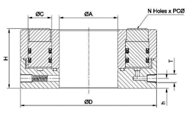
Hydraulic Load Cells are robust indicators that calculate axial compressive forces with median accuracy. The force is transferred from over pressure pistons and the hydraulic fluid to a manometer with a Kg indicator scale. The measuring system is automatic, so there is no need of external or additional energy. Static and dynamic forces can be detected in numerous applications of mechanical engineering in an easy and economically.
The hydraulic force measuring system is maintenance-free under normal operating conditions. In case of a leak, or in case the pistons don't stick out 1mm in average before measurement, the force measuring system has to be repaired. The force measuring system has to be checked for measurement accuracy at least every 2 years. In case the force values vary from the specification too far, the unit has to be repaired.
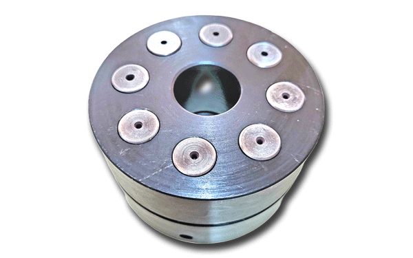
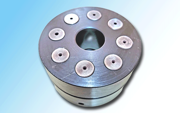
The Load Cells are designed on the basis of the multi-piston- system. The compressive forces are transferred over several small pistons to the hydraulic fluid. The Load Cells are with floating piston construction and with special piston seals guarantee an enduring and hermetic sealing of the fluid media.
During measurement, ensure that all pistons are perpendicular to the measuring surface with the complete pressure load area. All pistons have to stick out at least 1mm in average before measuring. To ensure flawless measuring, the manometer connection and the lock or fill screw should not be removed. Load Cells are useless for measuring strong pulsating forces or high accelerations.